Instrument View
Display the instrument measurement readings and configure measurement settings.
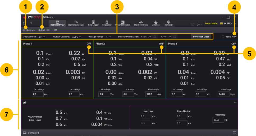
| 1 | Show or hide the Settings panel which lets you configure all available measurement settings for the instrument. | |
| 2 | Enable or disable all outputs. | |
| 3 | Change the instrument basic settings. See Basic Settings for Instrument. | |
| 4 | Check Basic View to display basic measurement readings only. See Phases Display. | |
| 5 | Show the output status. | |
| 6 | Show measurement readings for each phase. Specify settings for each phase such as output voltages. See Phases Display. | |
| 7 | Show the measurements and settings that apply to all phases when Output Mode is set to 1P3W or 3P. Changes to settings in this panel will be applied to all phases. Click the drop-down arrow at the upper right corner of the All panel to hide or show this panel. See "All" Panel Display and Settings. |
Phases Display
Show measurement readings for each phase.
The display elements for Basic View varies depending on the selected Measurement Mode settings. The display elements highlighted in bold are the example of default display for Basic View when Measurement Mode is set to VACDC and AACDC.
| VRMS | RMS voltage |
| VAC | AC voltage |
| VDC | DC voltage |
| ARMS | RMS current |
| AAC | AC current |
| ADC | DC current |
| W | Total power |
| VA | Apparent power |
| VAR | Reactive power |
| PF | Power factor |
| CF | Crest factor |
| VPK | Voltage peak |
| APK | Current peak |
Individual Phase Settings
The available settings vary depending on the instrument's settings.
Click the AC Voltage, DC Voltage, Frequency, and Phase Angle fields to specify the settings for each phase individually.
Basic Settings for Instrument
For advanced settings, see Instrument Settings.
When the output is on, you cannot change the following settings. To change the settings, turn the output off.
| Output Mode | Select output mode: 1P – Single phase output 1P3W – Single-phase three-wire output 3P – Three-phase output |
| Output Coupling | Select output coupling: ACDC – AC superimposed on the DC output AC – AC output DC – DC output |
| Voltage Range | Limit the output voltage range: L– AC: 0 V to 161 V, DC: –227.5 V to +227.5 V H – AC: 0 V to 322 V, DC: –455 V to +455 V |
| Measurement Mode | VACDC – Display RMS voltage. VAC – Display AC component voltage. VDC – Display average (DC) component voltage. VPK – Display peak voltage. AACDC – Display RMS current. AAC – Display AC component current. ADC – Display average (DC) component current. APK – Display peak current. |
| Protection Clear | If a protection function is triggered, remove the condition that caused the protection fault, then click Protection Clear to reset the protection. |
"All" Panel Display and Settings
Show the measurements and settings that apply to all phases. This All panel will be displayed only when Output Mode is set to 1P3W or 3P.
Left Panel Display
ACDC Voltage (Line - Line) – Line-to-line voltage between the indicated phases (phase 1 to 2 (V12), phase 2 to 3 (V23), phase 1 to 3 (V31)).
WTOTAL – Total power in Watts.
VATOTAL – Total apparent power in VA.
PFTOTAL – Total power factor.
Right Panel Settings
Specify the same value for all phases. The settings will overwrite any previous settings in the individual phase settings.
Line - Line – Line-to-line voltage for AC and DC. Note that the line-to-line DC voltage (VDC) cannot be set if the Output Mode is set to 3P.
Line - Neutral – Line-to-neutral voltage. The Line - Neutral will be unavailable when you have manually set each phase individually.
Frequency – Output frequency for AC and ACDC mode, regardless of whether the output is on. The frequency can only be set in this All panel, and applies to all phases.